Jason Nguyen
June 20, 2024
LED Regulator Circuit
I designed a simple LED regulator circuit to power a 3W LED from a 12V source using altium designer.

Designing an LED Regulator Circuit: My Journey from KiCad to Altium Designer
As an electronics geek, I am constantly seeking for new projects to push myself and broaden my knowledge. Recently, I wanted to create a simple LED regulator circuit that can power a 3W LED from a 12V supply. What made this project so fascinating was my switch from KiCad to Altium Designer, which I did after learning about Altium’s reputation as an industry standard in PCB design.
The Project Idea
The idea was simple: design a circuit that effectively power a 3W LED from a 12V source. To increase its adaptability, I designed it as an Arduino hat. This technique not only met the urgent requirement for LED regulating, but it also allowed for future integration with numerous Arduino applications.
Switching to Altium Designer
I’ve used KiCad for a while now, and it’s served me well. However, I kept hearing about Altium Designer being the industry standard, and I was curious to see what it offered. The transition was definitely a learning experience.
Here’s what I found:
- The user interface in Altium took some getting used to, but once I oriented myself, I found it quite intuitive.
- Altium’s component libraries are extensive, which saved me a lot of time in selecting parts and creating footprints.
- The real-time design rule checking in Altium was more comprehensive than what I was used to. It caught potential issues early in the design process, which was really helpful.
- The 3D visualization feature was not just cool to look at - it was genuinely useful for checking component clearances and envisioning the final product.
The Design Process
Creating the LED regulator circuit in Altium was a smooth process once I got the hang of the software. Here’s how it went:
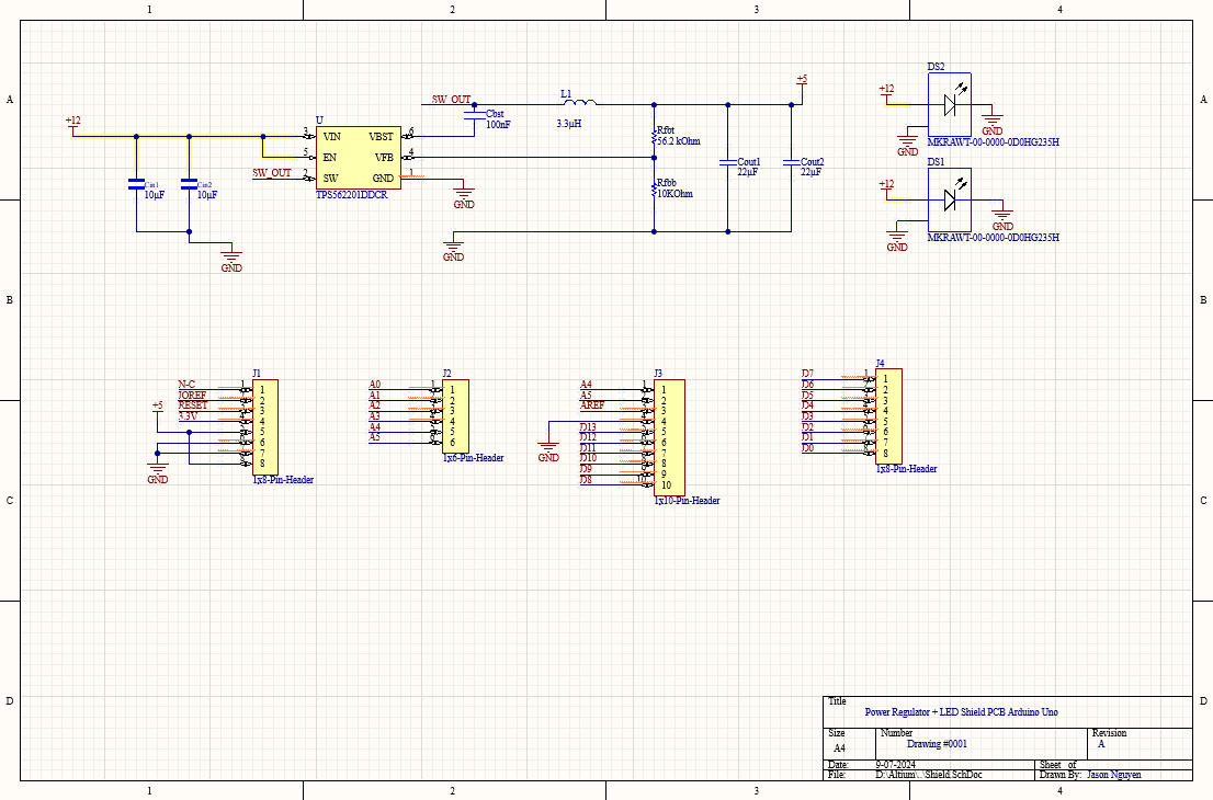
- I started with the schematic design, laying out the circuit and selecting components from Altium’s libraries. FOr the LED regulator circuit. I went to Texas Instruments’ website power supply design and found an appropriate regulator buck TPS562201DDCR. I then designed the rest of the circuit around this IC, including input and output capacitors, resistors, and connectors.
- Moving from schematic to PCB layout was seamless. I particularly appreciated Altium’s interactive routing capabilities.
- Designing it as an Arduino hat required careful planning to ensure proper alignment with Arduino pins. Altium’s precise measurement tools were really useful here.
- Throughout the process, I ran multiple design rule checks. This helped me catch and correct issues early, saving time in the long run.
